RMS-200v2 has general purpose I/O pins and Buttons for custom applications!
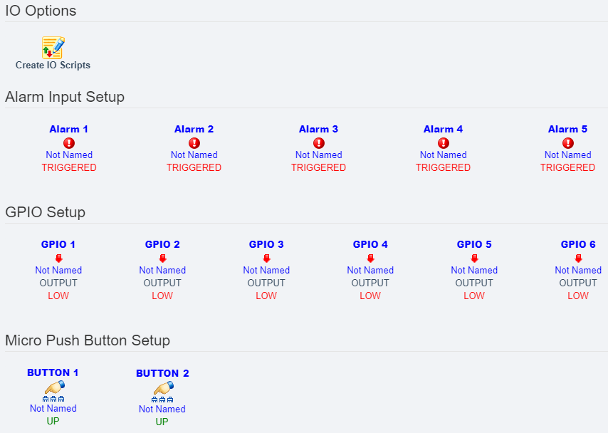
Below is a screen shot of the RMS-200v2 I/O overview page. Here you can choose which of the boards Alarm or I/O pins to control. RMS-200v2 has five dedicated Alarm Input Pins that have a corresponding LED. Use them with common door contacts to monitor entry points, or use them for solar panel theft prevention. RMS-200v2 also has six general purpose pins that can be set as Inputs or Outputs. These multi purpose I/O pins can be controlled or read from either the web page interface or a command shell. RMS-200v2 also has one micro push button that has special attributes when the RMS-200v2 board is booting. After the RMS-200v2 board is finished booting the button is free for you to use for controlling your devices.
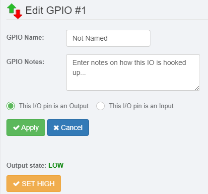
Below is a screen shot of the RMS-200v2 I/O setup page for GPIO 1 when at the default state of an output. GPIO pins can be configured to be 3.3 volt Inputs or Outputs. Use output pins to control any manner of devices.
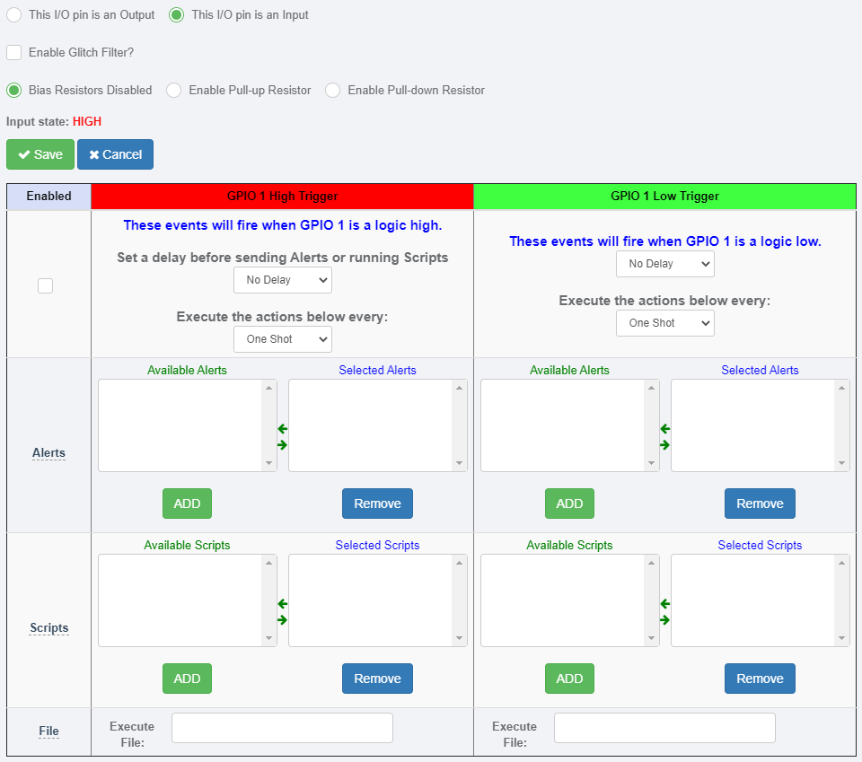
Below is a screen shot of the RMS-200v2 I/O setup page for GPIO 1 when when configured as an Input. Input pins can sense condition changes and react with alerts or scripts. Pull up and pull down bias resistors can be enabled to give the input pin a default state.
Below is a pinout diagram of CON 2 on the RMS-200v2 board. These are 3.3 volt general purpose I/O pins.

Pin 1 is VDD (3.3 volts).
Pin 2 is General Purpose I/O pin 1.
Pin 3 is General Purpose I/O pin 2.
Pin 4 is General Purpose I/O pin 3.
Pin 5 is General Purpose I/O pin 4.
Pin 5 is General Purpose I/O pin 5.
Pin 5 is General Purpose I/O pin 6.
Pin 6 is GND.
Below is a pinout diagram of the Alarm pins on the RMS-200v2 board. These input pins are pulled up to 3.3 volts.
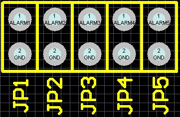
JP1 - Pin 1 is Alarm input 1. Pin 2 is GND.
JP2 - Pin 1 is Alarm input 2. Pin 2 is GND.
JP3 - Pin 1 is Alarm input 3. Pin 2 is GND.
JP4 - Pin 1 is Alarm input 4. Pin 2 is GND.
JP5 - Pin 1 is Alarm input 5. Pin 2 is GND.
Below is a picture of the RMS-200v2 user programmable push buttons. Use these buttons to manually control devices, or use them for onsite testing of alerts or scripts.

Below is a screen shot of the RMS-200v2 Push Button 1 setup page. Add email alerts and run custom scripts or programs when the button is pushed.

Button 1 Note:
When the RMS-200v2 is booting up it first checks to see if Button 1 is being held
down. If Button 1 is held down then all of the configuration files in /etc are re-written
bringing the RMS-200v2 unit to a factory default condition.
Button General Note:
When the ALARM LEDS on the RMS-200v2 board perform a flashing sequence, the
Linux OS has fully booted and normal button operation can commence.
Expansion Port
Below is a screen shot of the RMS-200v2 Expansion Port. The Expansion Port is a standard XBee socket. Not only can you install XBee devices, we also make our own expansion port devices that can be enabled under the devices menu. The com port is available at /dev/ttyS3

LCD Port
Below is a screen shot of the RMS-200v2 LCD Port.
The LCD port is designed for use with ™Nextion Touch Screen LCD displays.
The LCD Port is a standard TTL serial port available at /dev/ttyS2.
The TX/RX pins are 3.3v only.
There is a 5v power pin and a Ground pin to power the LCD display.
Users can make their own LCD touch screen Interface using the
™Nextion LCD Editor.
Check out our LCD project tutorial.

Our Story
EtherTek Circuits started its business in 2001. Ever since we have provided remote monitoring and control solutions for Remote Tower Sites, the Oil & Gas industry, Telemetry systems for Agriculture, Municipalities, Mines, Solar Farms, Hydro Plants, and the Military.


