Prototype with the ATTiny85 and ADS1115
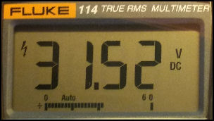
Recently a client of ours required a small microcontroller to monitor voltage from 0 to 35 volts DC with 2 decimal place accuracy. The ATTiny85 by Atmel is perfect for simple jobs like this. It is inexpensive, readily available, and small in size. The built-in 10 bit ADC of the ATiny85 wasn't going to cut it due to the large voltage range required. The ADS1115 16 bit ADC by TI seemed like a good fit and Adafruit has a development breakout board. There were some extra steps to get this working properly with the hardware development tools chosen so this article is for our reference and hopefully you may benifit from it also.
Hardware and Components used
To develop for the ATTiny85 we purchased the
Tiny AVR Programmer by SparkFun.
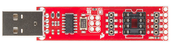
Not only does this nifty USB device program the Tiny AVR, it breaks out the IC pins to
female headers so you can easily prototype around the ATtiny chip without having to pull it out and
plug it in over and over. Another nice feature is that you can use the Arduino platform and
IDE to develop code and upload it to the ATiny85.
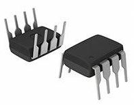
Obviously you will need some ATiny85 MCU's to test with, also purchased from SparkFun.
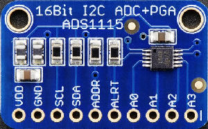
Adafruit makes a nice ADS1115 16 bit ADC breakout board that fits into a standard bread board for ease of prototyping.
The breakout board comes with pull up resistors on both the data and clock lines.
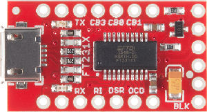
Sparkfun makes a nice Serial Breakout Board used for displaying the voltage readings on our PC.
Software needed
This is a list of software we used to make this work. Our development platform was Windows 10.
We keep an archival copy of the software. The reader must be familiar with how to install the Arduino IDE and be able to
install the required libraries. The reader must also know how to
install the windows usb driver for the Tiny AVR Programmer.
Arduino IDE version 1.6.13 archived.
USB Tiny ISP Driver v1.2.6.0 archived.
ATTiny Core archived.
Tiny Wire (Master) Library archived.
Adafruit ADS1115 Library archived.
Getting Started
SparkFun supplies a well written
hook-up guide
for the Tiny AVR Programmer. In the section
Step 1: Download the ATtiny Addon we were not able make the ATiny Hardware
definitions work for some reason so we insatlled the
ATTiny Core by Spence Konde. However, following the rest of the tutorial is straight forward and we are soon
able to upload the Blink LED Sketch and verify the ATiny Programmer is working correctly.
Next we installed the TinyWire Library to prepare for I2C communications to the Adafruit ADS1115
breakout board. We then installed the Adafruit ADS1115 library. According to the
Adafruit github page
communication to the ADS1115 breakout board must use the Atiny85 pin PB0 for SDA and pin PB2 for SCL and the
Atiny85 must run at 8MHz. In the Arduino IDE, set the Atiny85 clock to 8MHz Internal and then
click Burn Bootloader. Our ADC test code fails with compile errors because the ADS1115 library expects to
use the Wire Library not the TinyWire Library we need.
Library Code Modification
The ADS1115 library was designed
to work with the Arduino Wire Library, but we need to modify it to work with the TinyWire Library.
You may modify the Adafruit_ADS1015.cpp file and Adafruit_ADS1015.h file by hand or
download our modified files.
The code now compiles without errors.
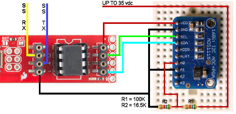
Wiring Diagram
We plugged the ADS1115 breakout board into a bread board and wire it up as shown below.
We used the Software Serial (SS) Library with pins 3 and 4 connected to the Serial Breakout board to view the voltage readings on our PC.
Upload Code to the ATiny85
We then proceed to upload our ADC test code into the Atiny85 and found that the SDA line being pulled high
by the ADS1115 breakout board was causing bus contention and making the chip programming process fail. Disconnecting the SDA line
during the programming procedure solves the problem - a minor annoyance. At this point we can burn our ADC
test code to the ATiny85 but it doesn't work.
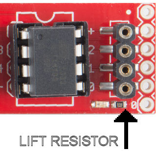
Hardware Modification
We found we needed to make a modification to the Tiny AVR Programmer. The SDA line is being pulled low with a resistor and LED causing I2C communication to fail. With a soldering
iron and a bit of flux, we lift the resistor on one side to break the connection to ground. This also disables the LED but allows the ATTiny85 to communicate with the
ADS1115 breakout board. It would have been nice if the Tiny AVR Programmer had a jumper to disable the
LED.
The Code
After the code has been uploaded to the Atiny85 it executes faster than you can
reattach the SDA line. This causes the I2C code to crash and produce incorrect ADC readings. Simply
reconnect the SDA line and then pull the Tiny AVR Programmer from its USB socket and plug it back in again to fix the I2C crash.
Adding a 5 second delay at the top of the setup function gives enough time to reconnect the SDA line before any I2C code executes thus avoiding unplugging and reinserting the Tiny AVR Programmer.
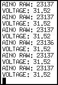
Conclusion
Success. Below is a screen shot of the serial output and our ADC test code. It is amazing how much can be done with these amazing tiny microcontrollers!
			*********************

			*   ADC TEST CODE   *

			* EtherTek Circuits *

			*********************


			//DEFINES

			#define DEBUG 1 //Set to 1 for debugging messages to serial port, Set to 0 for production.

			#define Rx 3  // this is physical pin 2

			#define Tx 4  // this is physical pin 3


			//INCLUDES

			#if DEBUG

			  #include <SoftwareSerial.h> //debugging

			#endif

			#include <Adafruit_ADS1015.h>


			//DECLARATIONS

			#if DEBUG

			  SoftwareSerial mySerial(Rx, Tx);

			#endif

			Adafruit_ADS1115 ads;


			//VARIABLES

			float voltage;

			int16_t adc0;


			void setup()

			{

				delay(5000); //5 seconds to plug in the SDA line

			  #if DEBUG

			   pinMode(Rx, INPUT);

			   pinMode(Tx, OUTPUT);

			   mySerial.begin(9600); //debugging

			  #endif

			  ads.begin();

			}


			void loop()

			{

			  //read voltage

			  adc0 = ads.readADC_SingleEnded(0);

			  voltage = (adc0 * 0.1875)/1000;

			  voltage = voltage * 7.265;

			  #if DEBUG

			   mySerial.print("AIN0 RAW: "); mySerial.println(adc0); //debugging

			   mySerial.print("VOLTAGE: "); mySerial.println(voltage); //debugging

			  #endif

			  delay(250);

			}
Our Story
EtherTek Circuits started its business in 2001. Ever since we have provided remote monitoring and control solutions for Remote Tower Sites, the Oil & Gas industry, Telemetry systems for Agriculture, Municipalities, Mines, Solar Farms, Hydro Plants, and the Military.


