Windows Client
The Windows Client program is used to control the relays on
the USB Relay board from a Windows computer. An installer program is provided. Follow the examples below to have the software installed on your computer.
Software Installation
Using the Windows Client
When starting the client program for the first time, it looks to see if a board has
previously been connected. If not, the add device dialog box pops up. This list is
automatically populated with however many USB Relay boards that are found to be connected
to the host. Each USB Relay board is programmed with a unique identifier. The "Refresh"
button will re-poll the USB port and find any units plugged in. NOTE: Windows
Vista and Windows 7 users may have to run the client program as Administrator.

Select the desired unit and hit the "ADD" button. The selected device has now been added to
the database. The main program will now appear.
If the "Add Device" dialog box is closed without selecting a device, the main program will
still open, however, a device will still need to be added in order to poll information. To
add another device, click the "ADD Device" button. If there are multiple USB Relay boards
in the list, you may make one default (shows up in the list box first) by selecting the
"Set Default" button. If at any time you wish to remove a device, have the desired device
selected in the drop-down menu and click the "Delete Device" button.
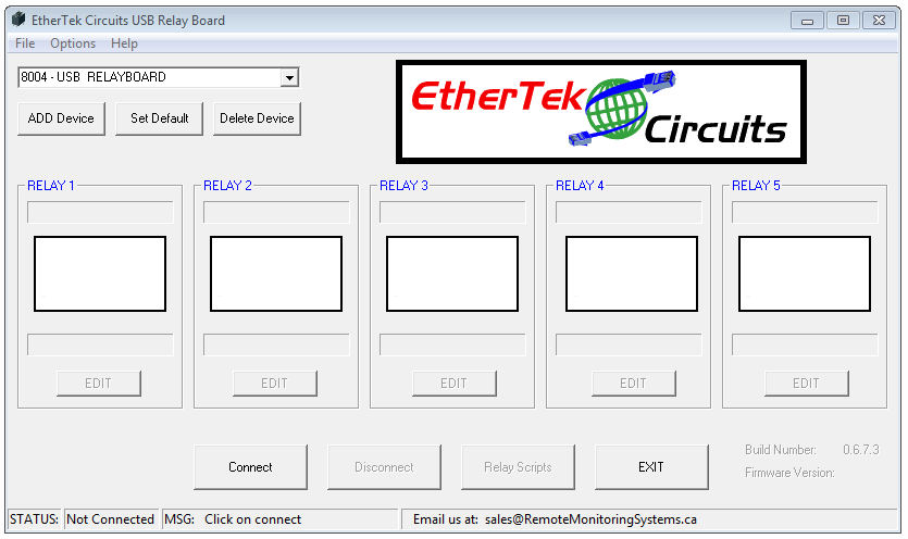
To start polling information, select the desired device from the drop-down menu and click
on "Connect"
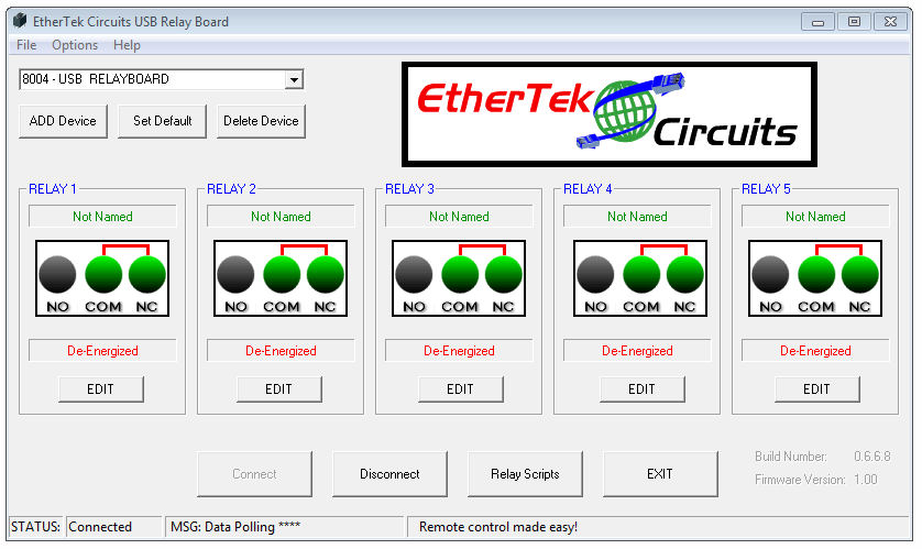
The program will connect to the USB Relay board selected and display the relay status on
the main screen. The default state of each relay is COM and NC. Energizing a relay will
make it COM and NO. If a relay is energized, and then the USB cable is disconnected, all
relays will revert to the de-energized state (COM and NC). When a relay is energized, a
corresponding LED will illuminate on the PCB. A few other main features are displayed on
the main page such as:
Name - Displays a name given to the relay. 25 Characters MAX.
Relay - Displays a graphical representation of the current relay state (NO or NC).
State - Displays a name given to the relay when it is energized or de-energized.
Relay Scripts - Allows complex relay actions with simple commands.
Holding the mouse pointer over the relay icon will bring up a tool tip which contains notes
about how the relay is hooked up.
If any of these settings needs to be changed, or if more advanced features are needed,
click on the "Edit" button. Each edit button is only applicable for the relay of whichever
group it is in. In the example below, the "Edit" button for relay 1 is clicked.
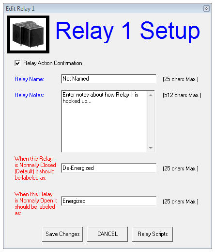
The Edit Relay Dialog pops up. Each of the features are:
Relay Action Confirmation - When this is selected, confirmation will be needed on each
relay action. If Relay Action Confirmation is not selected, then relay actions are
immediate.
Relay Name - Enter a descriptive name for this relay.
Relay Notes - Enter some notes that describe the function of this relay.
Normally Closed State - Enter text that represents the Normally Closed state of the
relay.
Normally Open State - Enter text that represents the Normally Open state of the relay.
Relay Scripts
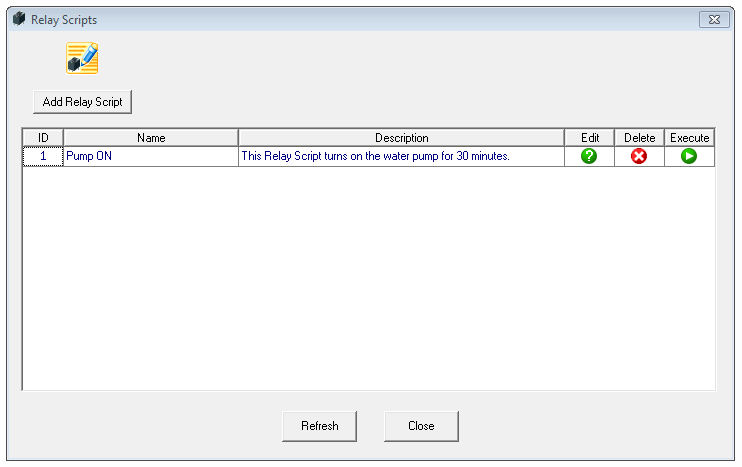
Relay scripts are made up of simple commands that control the relays. Complex relay actions
can be performed to control your equipment. The screen shot below shows the Relay Scripts
dialog box. This dialog box shows the list of current relay scripts stored in the database
and provides a way to execute, edit, and delete them.
To edit a relay script, double click on the green edit button to be taken to the dialog box
below.
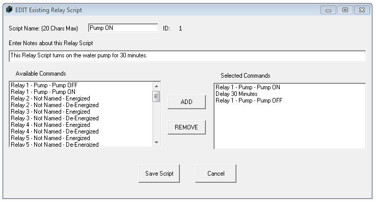
Relay scripts are built using available comands from the left box and adding them to the
selected commands on the right.
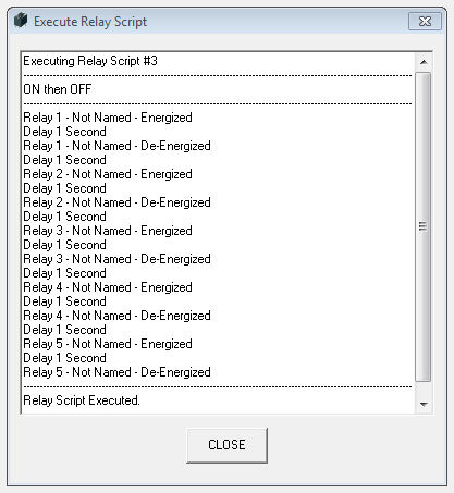
To execute a relay script, double click on the green execute button on the Relay Scripts
dialog box. The screen shot below shows a relay script executing commands.
Power Saving Features
If power draw on the USB port is a concern due to many devices plugged in, JP1 (LED ENABLE)
may be removed from the USB Relay circuit board. Removing JP1 will disable the power
indicator LED.
If more power saving is desired, selecting the "Options" pull down menu from the main
screen and then clicking on "Relay Options" will bring up the dialog box shown below.
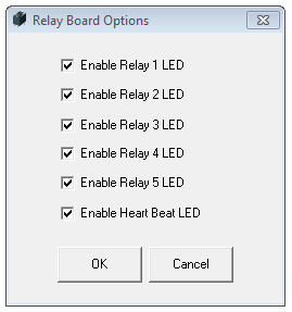
To disable LEDS for each realy and the "Heartbeat" LED, simply uncheck the corresponding check box and then click the OK button. The LED options are preserved even when the USB Relay board has been power cycled.
Our Story
EtherTek Circuits started its business in 2001. Ever since we have provided remote monitoring and control solutions for Remote Tower Sites, the Oil & Gas industry, Telemetry systems for Agriculture, Municipalities, Mines, Solar Farms, Hydro Plants, and the Military.


