RMS-100 has three 24 bit isolated voltmeters for sampling DC voltages up to 100 volts!
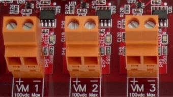
Each voltmeter is capable of measuring up to +/- 100 VDC with 24-bit accuracy. Each voltmeter has its own
24 bit Delta Sigma ADC.
The data and power lines for each voltmeter are isolated with a chip-scale air core transformer.
This enables each voltmeter to measure different DC voltage sources without any effect on the main board or other voltages.
This technology enables the ability to measure (but not limited to):
- positive and negative voltages
- separate power sources
- individual batteries in a battery bank
- shunt voltages for equipment that may be drawing or generating power.
- solar panel voltage and amperage
- wind turbine voltage and amperage
- battery charger voltage and amperage
Each voltmeter has a Mode Jumper that when removed puts the voltmeter into low voltage mode. In this mode, the volmeter has a range of +/- 2.0 VDC and has over 4 million steps. This is perfect for calculating amperage by measuring voltage drop across a current shunt.
Note 1: Voltmeters that have nothing hooked up to them so that the positive and negative inputs are floating may read spurious positive and negative voltage readings, this is normal. You may dampen the voltage reading by sacrificing accuracy using the precision box. Use a number between 2 and 6 to increase or decrease the decimal place.
Note 2: Due to variations in components and the manufacturing process, voltmeter readings may differ slightly from each other and from your hand held DVM. Use the adjustment box to fine tune the voltmeter to display the expected value.
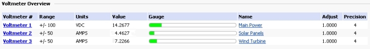
Below is a screen shot of the RMS-100 voltmeter overview page. This page shows at a glance all voltmeter readings and provides a gateway for more voltmeter options. In the screen shot below voltmeter 1 is displaying a positive reading of a 12v battery bank. Voltmeter 2 is in ammeter mode, it is measuring the charge going into the battery bank via a 50 millivolt / 50 amp current shunt (more on using shunts below). Voltmeter 3 is measuring the output of a negative 24 volt power supply. Note: A green bar graph indicates positive voltage, a red bar graph indicates negative voltage. To refresh the web page you can press the Refresh button. To have the web page automatically refresh, set the refresh rate. The graphs button takes you to a page displaying voltage or amperage readings.
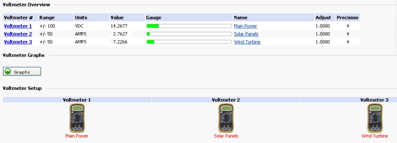
Clicking on one of the voltmeter icons will bring you to the setup page for that particular voltmeter.
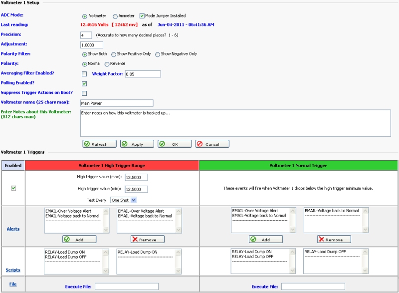
Here you can enter setup information like a name and notes for this voltmeter.
The "Scale Mode Jumper" check box lets the RMS-100 know if the mode jumper is installed or removed.
The precision box is used to set how many decimal places to display, valid choices are between 2 and 6.
The adjustment box is used to fine tune the voltmeter to match your DVM reading.
The Polarity filter is used to filter out unwanted positive or negative readings.
The Polarity Filter will allow both positive and negative, positive only, or negative only readings.
The Polarity setting is used to reverse the polarity of the voltage being read.
The Averaging Filter is used to smooth out the voltage readings.
The Polarity setting is used to reverse the polarity of the voltage being read.
The averaging filter will settle the voltage bounce readings. The weight factor should be between 0 and 1.
The larger the number, the faster the answer is obtained. The lower the number, less bounce occurs.
A good default is 0.05 if the precision is set to 6. The averaging filter uses the formula below.
C = w(C-P)+P
C = Current voltage reading
P = Previous voltage reading
w = Weight factor (as determined by value entered into the Weight Factor text box)
The "Suppress Trigger Actions on Boot" check box is used to stop actions from happening when the RMS-100 board is warm or cold started, or when settings are changed. Each voltmeter has a High, Normal, and Low trigger range. Each trigger range has a maximum and minimum value. The range in between the maximum and minimum value acts like a dead band area. Triggers can be set to fire alerts or scripts when the voltage is either too high or too low. The High Trigger is used when the voltage rises above the High Trigger maximum value. The Normal Trigger is used when the voltage falls below the High Trigger minimum value. The "Execute Every" box is used to select how often the condition should be tested and acted upon. Each voltmeter trigger can also execute a custom file stored on the RMS-100 board.
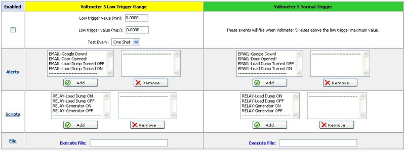
Below is the Low Trigger interface. The Low Trigger is used when the voltage falls below the Low Trigger maximum value. The Normal Trigger is used when the voltage rises above the Low Trigger minimum value.
Voltmeter Triggers Explained
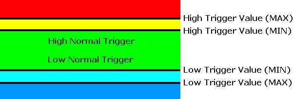
When a voltage is within a trigger range (as shown by the different color bands),
the action will only execute as often as specified by the "Execute Actions Below Every" pull down list box.
If a voltage is in the green (Normal Range), and moves above the High trigger value (MIN) into the yellow, no actions occur.
Only if the voltage moves into the red range (past High Trigger Value (MAX)) will the action occur.
If the voltage flutters into the yellow and back into the red, this does not reset any triggers.
The High Trigger condition will reset only when the voltage falls back into the green where it will execute
the "High Normal Trigger" action only once.
The same theory applies to the Low Trigger values. If a voltage is in the green (Normal Range), and moves below the Low trigger value (MIN) into the light blue, no actions occur. Only if the voltage drops into the dark blue range (past Low Trigger Value (MAX)) will the action occur. If the voltage flutters into the light blue and back into the dark blue, this does not reset any triggers. The Low Trigger condition will reset only when the voltage rises back into the green where it will execute the "Low Normal Trigger" action only once.
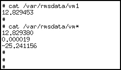
Voltmeters on the Command Line
Below is an example of reading the voltmeters on the command line. Note: the voltmeter readings are stored in files located in the /var/rmsdata folder. Voltmeter 1's storage file is called vm1. Voltmeter 2's storage file is called vm2 etc.
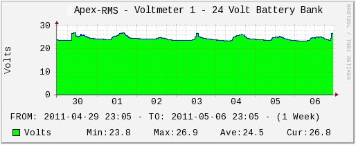
Voltmeter Graphs.
Each voltmeter has corresponding graphs associated with it.
Below is a graph showing volts over a 1 week period. Day, week, month, and year graphs are available.
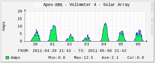
Below is a graph showing voltmeter 4 in amperage mode. At one point during a 1 week period, the solar panels were putting over 12 amps into the batteries.
How to Measure amperage using a shunt.
If you are managing a remote battery powered site, knowing your battery voltage is vital. It is also a key thing to know how much charging you are putting back into your batteries, and how much power is being consumed by your equipment. Using a common shunt, it is possible to obtain a millivolt reading that relates to an amperage reading. The voltmeters on the RMS-100 board are perfect for this as they are very sensitive and can easily read millivolt readings.
A word on shunts.
Shunts are defined as a resistive load through which electricity is diverted. Often the resistance of a shunt is known precisely and is used to determine amperage by measuring the voltage drop across it using Ohm's law (I = V/R). It also allows high current measurements with low-current equipment. Some popular shunts are 50mv/50amp and 100mv/100amp. The relationship between the millivolt reading and the current going through the shunt makes figuring out the amperage easy. For example, in the case of the 50mv/50amp shunt: if you had 50 amps of charging going through the shunt then the millivolt reading would be 50mv. If you had 25 amps of charging going through the shunt then the millivolt reading would be 25mv etc etc. When measuring current over 100 amps, continuous operating current should not exceed 2/3 ammeter shunt rating. To ensure proper operation, the shunt temperature is in no way to exceed 145° C, as a permanent change in resistance will occur. For example, if continuous current for an application is 500 amps, the ammeter shunt rating should be no less than 750 amps. This applies to both 50 and 100 millivolt current drop shunts.
To learn more about shunts and how much they cost, please visit:
U.S.A. www.deltecco.com
Above is a drawing of a 50mv/50amp shunt.
So where does RMS-100 fit into all of this?
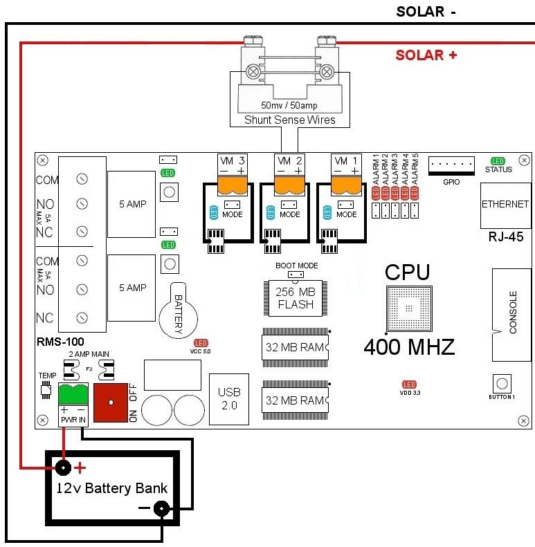
Below is an example diagram of how to use RMS-100 with a shunt to measure charging from a solar panel array.
The negative solar panel lead is connected to the battery negative terminal. The positive solar panel lead
is routed to the positive battery terminal by way of a 50 millivolt 50 amp current shunt. From one side of the
shunt there is a sense wire run to the negative input on VM2. From the other side of the shunt there is a sense wire run
to the positive input on VM2.
NOTE: Consult the Owners Manual or the Manufacturer of the equipment you are measuring to
determine if there is any preference on which power wire the shunt should be hooked up to.
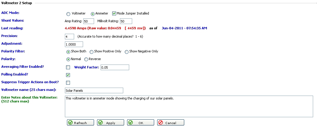
Below is a screen shot of how to setup Voltmeter 2 to act as an ammeter to show how much charging is going into the
batteries from solar panels. First, put Voltmeter 2 into ammeter mode and click Apply.
Next, enter valid shunt values (amperage rating, millivolt value), enter name and
notes and then click Apply or click Ok.
If everything is hooked up correctly you should be able to see how much amperage is being put into your batteries. In the screenshot below the 12 volt main battery bank is being charged by both solar and wind. This technique can be used to measure DC current being put into your batteries by solar panels, a wind generator, or a battery charger. RMS-100 can monitor your voltage and amperage remotely and alert you to dangerous battery conditions.
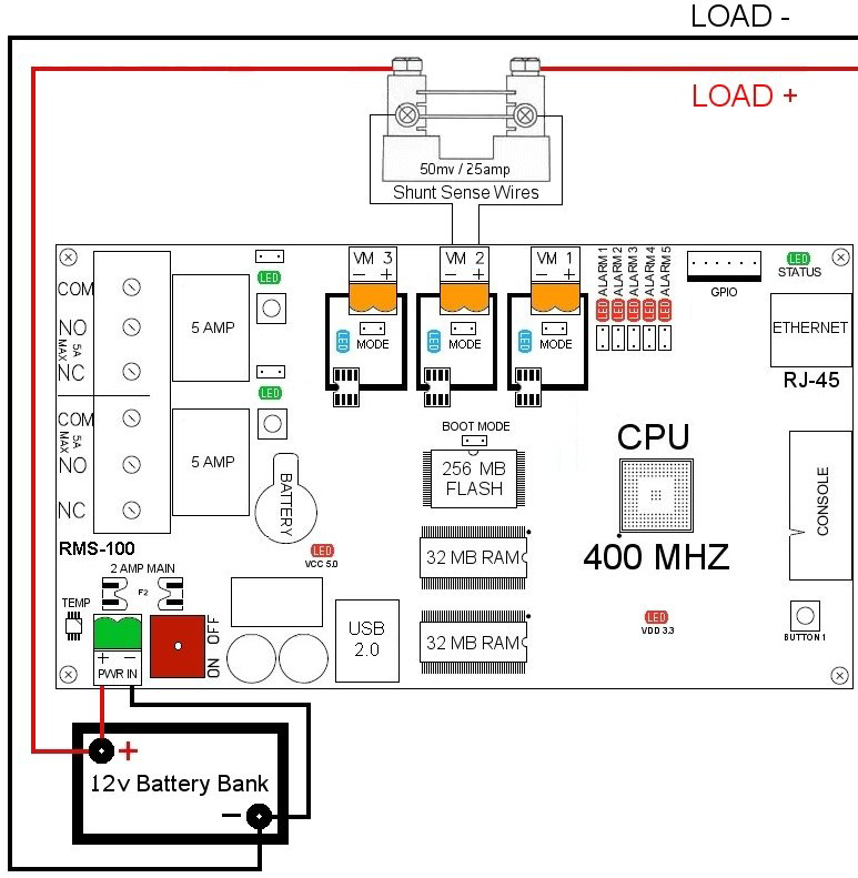
Below is an example of how to use RMS-100 with a shunt to measure current draw from your equipment.
The negative load wire is connected to the battery negative terminal. The positive wire
is routed to the positive battery terminal by way of a 50 millivolt 25 amp current shunt. From one side of the
shunt there is a sense wire run to the negative input on VM2. From the other side of the shunt there is a sense wire run
to the positive input on VM2.
NOTE: Consult the Owners Manual or the Manufacturer of the equipment you are measuring to
determine if there is any preference on which power wire the shunt should be hooked up to.
The electrical ratings for the voltmeter terminal blocks can be found here.
RMS-100 is a remote voltage monitoring system with many features to give you the situational awareness to keep your equipment running reliably!
Our Story
EtherTek Circuits started its business in 2001. Ever since we have provided remote monitoring and control solutions for Remote Tower Sites, the Oil & Gas industry, Telemetry systems for Agriculture, Municipalities, Mines, Solar Farms, Hydro Plants, and the Military.


