Setting up RMS-300v2 Remote Monitoring System
Connect 8 - 60 volts dc power (minimum 500 ma) to the green terminal block that is beside relay 4 (See figure 1). Connect an Ethernet cable to the rj-45 jack on the RMS-300v2 board. It takes the RMS-300v2 board approximately 30 seconds to bring up the Linux operating system. The RMS-300v2 will signal it is ready by first blinking the green status light in a continuous heartbeat sequence. After a few seconds the red alarm leds will display a light sequence. The board is now fully booted up and is ready for configuration.
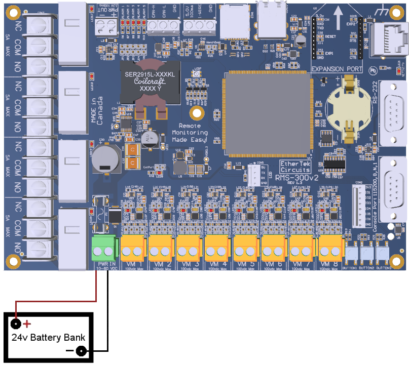
Figure 1
Note1: RMS-300v2 units should be mounted inside a steel enclosure that is grounded
properly to prevent Electro Magnetic Interference.
We recommend configuring RMS-300v2 before deploying it in the field. Simply plug
RMS-300v2 into your network or computer using an Ethernet cable (Straight or
Cross).
When the RMS-300v2 is turned on it boots the Linux operating system and uses the values stored in its configuration files to bring up the system. The default values consist of an IP address, username, and password. The default IP address is 10.10.10.10. The default username is root. The default password is pass.
Give your computer an ip address in the 10.10.10.X class. For instance use 10.10.10.1. Set
your computers Netmask to 255.255.255.0 There is no need to set a Gateway at this time.
Open your favorite web browser and enter 10.10.10.10 into the address bar, press enter or
the go button. You should be presented with a password box similar to the one below.
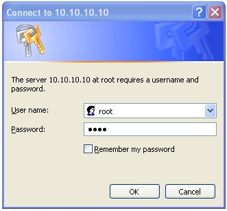
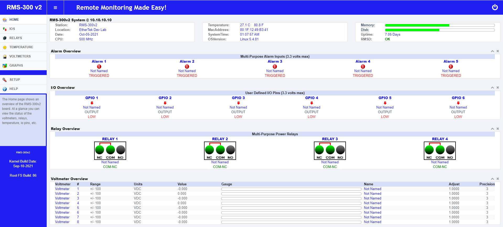
Enter in the default username and password then press the OK button. You will be taken to
the RMS-300v2 Home page. This page contains an overview of all of the functionality of
the RMS-300v2 remote monitoring board.
In the left side panel, click on the Setup icon. This takes you to the System Setup area
shown below.
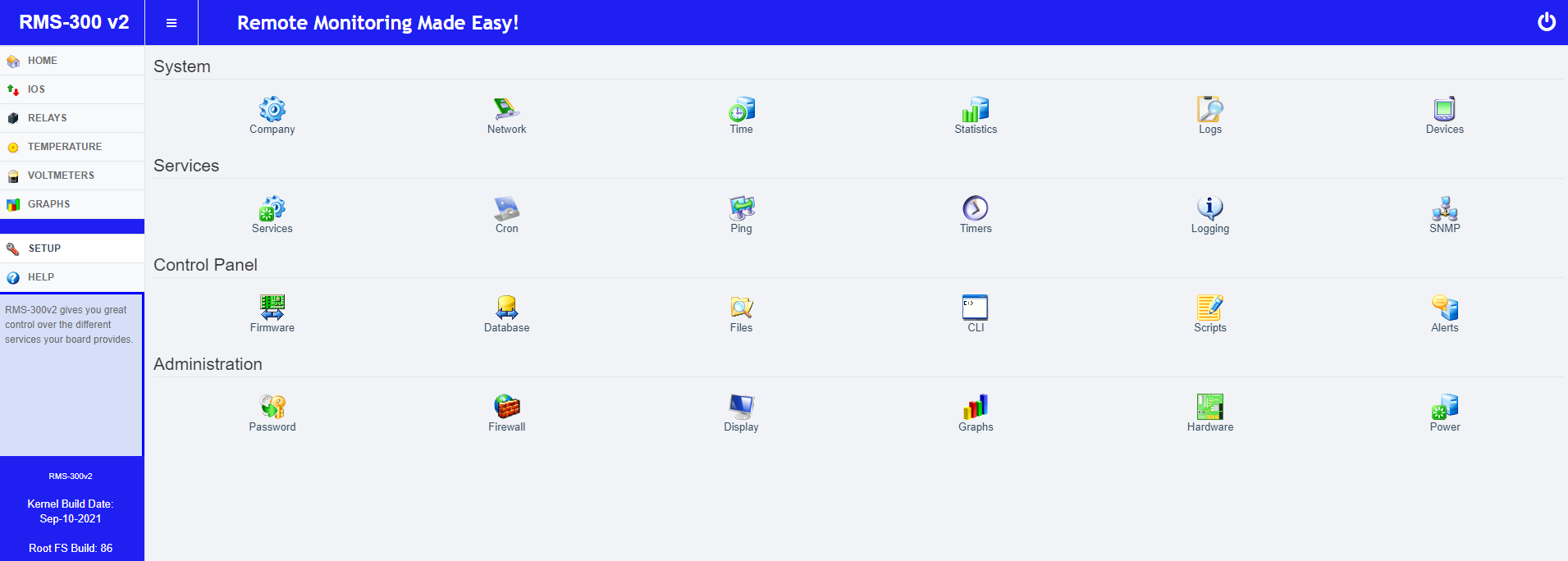
Here you will want to visit the following areas: Company , Network , System Time ,
and Password. Adjust the Station Name, Location, Domain Name,
IP Address, Subnet Mask, Gateway, DNS, and password you want the device to have. Caution
must be taken when configuring the device, entering incorrect values may cause you to lose
connectivity with the device, forcing the need for a factory reset. Once you have
RMS-300v2 configured properly, it is ready to deploy in the field. Below are some
basic examples of how to install the RMS-300v2 unit.
Installation
Basic Installation Example 1
Monitoring your Battery Voltage
To monitor your battery voltage over the internet, run a wire from the positive side of the battery bank to one of the Voltmeter positive inputs. Run a second wire from the negative side of the battery bank to the corresponding Voltmeter negative input as shown in Figure 2. Connect RMS-300v2 to the internet with a common Ethernet cable and monitor the voltage level of your battery bank with a web browser.

Figure 2
Basic Installation Example 2
Signal Strength on Proxim Microwave Radios
Radios that have an external RSSI port for checking signal strength can be monitored with
ease. Simply attach the RSSI output from the radio to one of the Voltmeter inputs on the
RMS-300v2 board (see Figure 3). Monitor the signal strength of your radios with a web
browser and/or have RMS-300v2 alert you by email if the signal falls below a certain
threshold.
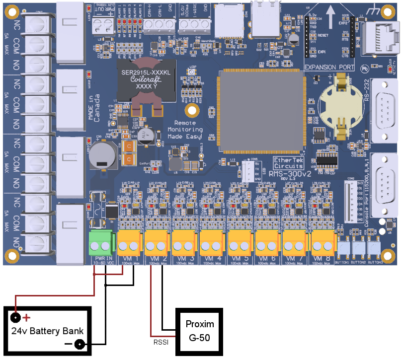
Figure 3
Basic Installation Example 3
Turning Devices ON/OFF
To power cycle any device remotely, simply cut one of the wires in the power cord
of a device. Attach one side of the cut wire to the COM terminal on one of the Power
Relays. Attach the other side of the cut wire to the NC (normally closed) terminal on the
corresponding Power Relay. Power cycle your device at any time using RMS-300v2.
Virtually any 1 to 240 volt AC or DC device can
be turned ON/OFF remotely this way. For devices that should be by default turned
off, use the COM and NO (normally open) configuration. Figure 4 illustrates just one of the
many ways you can set up devices for remote power cycle.
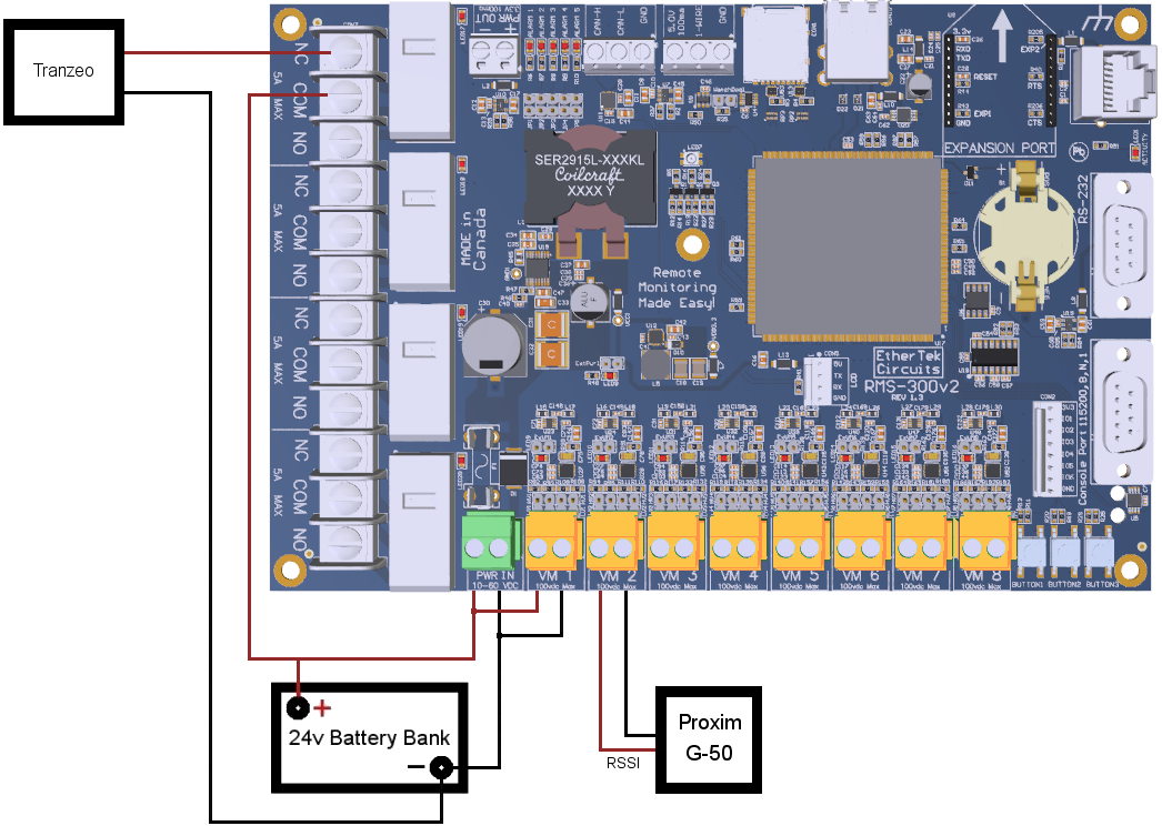
Figure 4
Basic Installation Example 4
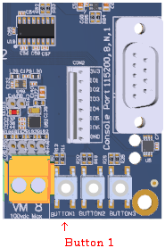
Using the Alarm pins to monitor door contacts
To give your equipment room some security you can use widely available common door
contacts. These contacts allow current to flow through them when they are in close
proximity with each other. RMS-300v2 can sense when the contacts are together or
apart. Program the alarm pins to send an email, run a custom file, and/or toggle a relay
when the door gets opened. The diagram below (figure 5) shows how to use Alarm pin 5 to
monitor door contacts. See our Projects Page for instructions on
how to use the alarm pins to help prevent
solar panel theft.
Note1: the LED5 light is on when the contacts are together. This is the armed
position.
Note2: each Alarm pin has a corresponding LED.
Figure 5
RMS-300v2 Hardware Screen Shot

Built in Graph Examples
The RMS-300v2 board comes with built in graphing software called RRDtool. RRDtool is the OpenSource industry standard, high performance data logging and graphing system for time series data. There is no need for an external server to make graphs based on RMS-300v2 readings. It is all done right on the RMS-300v2 board.
Main Battery Power on Apex Mountain
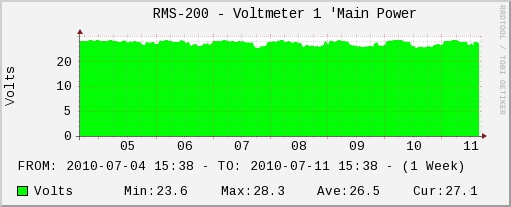
The graph above depicts main battery power at our wireless internet repeater site on Apex Mountain. Bumps in the graph represent charging from either solar panels or an Air403 wind turbine. Supplementary power is provided by a Honda Generator that is remote started with RMS-300v2. The 24v battery bank is monitored by RMS-300v2 and the graph is updated every minute. This provides a quick and easy way to check battery levels at anytime from anywhere a web browser is available!
Temperature Monitor on Roderick Dhu Mountain
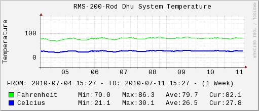
The graph above depicts room temperature at our wireless internet repeater site on Roderick Dhu Mountain. Dips or bumps in the graph represent temperature changes. The temperature of our equipment room is monitored by RMS-300v2 and polled every minute. This provides a quick and easy way to check temperature at anytime from anywhere a web browser is available!
System Work Load Monitor on Hedley Mountain
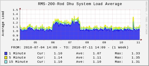
The graph above depicts system load of the RMS-300 at
our wireless internet repeater site on Hedley Mountain. Dips or bumps in the graph shows
how hard the processor is working. This provides a quick and easy way to check system
performance at anytime from anywhere a web browser is available!
RMS-300v2 is a remote site monitoring board with many features to keep your equipment running reliably.
Our Story
EtherTek Circuits started its business in 2001. Ever since we have provided remote monitoring and control solutions for Remote Tower Sites, the Oil & Gas industry, Telemetry systems for Agriculture, Municipalities, Mines, Solar Farms, Hydro Plants, and the Military.


