Device Overview
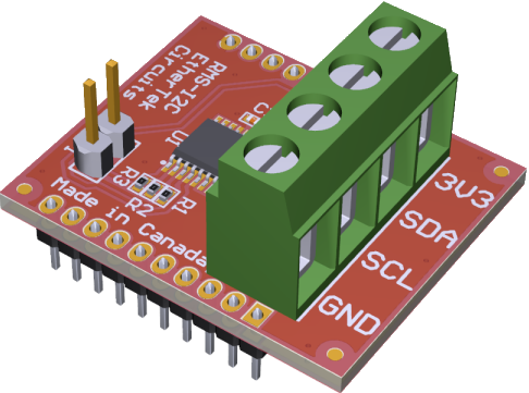
The EtherTek RMS I2C add-on board was designed for use with I2C sensors and other devices that
communicate over an I2C bus.

The RMS I2C add-on board serves as an interface between the RMSv2 UART expansion port and I2C-bus; this allows the RMSv2 board
to communicate directly with other I2C-bus devices using an SC18IM704 UART to I2C bridge IC. The SC18IM704
operates as an I2C-bus master. The SC18IM704 controls all the I2C-bus specific
sequences, protocol, arbitration and timing. The RMSv2 communicates with the SC18IM704 via
ASCII messages; this makes the control sequences from the RMSv2 to the
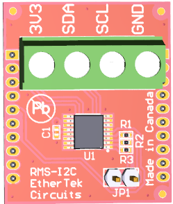
SC18IM704 become very simple. The RMS I2C add-on board has built in pullup resistors that can be enabled
by installing a jumper on the JP1 header pins. Remove the jumper to disabled the built in pullup resistors.
Read more about the SC18IM704 UART to I2C bridge controller IC here.
Setting up the RMS-I2C ADD-ON Board
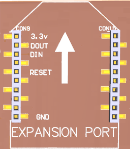
Make sure the power is disconnected from the RMSv2 board. Insert the RMS-I2C add-on board into
the expansion socket on your RMSv2 board. Make sure that the green header on the RMS-I2C add-on
board is closest to the outside edge of the RMSv2 board.


Make sure that all the pins on the RMS-I2C add-on board are inserted into the expansion socket on the RMSv2 board and that there are no pins hanging over the edge of the expansion connectors at the front or back. Make sure that the RMS-I2C add-on board is fully seated into the expansion socket on the RMSv2 board. Once you have confirmed that the RMS-I2C add-on board is correctly inserted into the expansion socket on the RMSv2 board, you may power on the RMSv2 board.
Testing the RMS-I2C ADD-ON Board
The RMSv2 board communicates with the RMS-I2C add-on board via serial.
- RMS-100v2 expansion socket uses /dev/ttyS1
- RMS-200v2 expansion socket uses /dev/ttyS3
- RMS-300v2 expansion socket uses /dev/ttyS3
To verify communication to the RMS-I2C add-on board, log into your RMSv2 board with SSH.
Use the built-in nanocom program to send a test command to the RMS-I2C add-on board.
The test command to send is uppercase VP. The SC18IM704 chip on the RMS-I2C add-on board
will immediately respond with SC18IM704 1.0.2 as shown below. Note: there is no space between the
VP command and the output from the SC18IM704 chip on the RMS-I2C add-on board.
RMS-100v2 example:
[root@RMS-100v2: /root# nanocom /dev/ttyS1 -b 9600 -p n -s 1 -d 8 -f n -e l
Press CTRL+T for menu options
****************************************Line Status***********************************************
9600 bps 8 Data Bits n Parity 1 Stop Bits n Flow Control l echo
**************************************************************************************************
VPSC18IM704 1.0.2
Programming the RMS-I2C ADD-ON Board
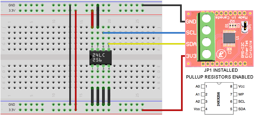
Before any code can be written, a test circuit is needed. To test reading and writing from the RMS-I2C add-on board we chose a 24LC256 EEPROM Memory IC in a DIP package. The diagram below shows how to wire up the test circuit on a bread board.

Things of note:
- A0, A1, and A2 on the 24LC256 chip are connected to GND and that gives an address of 0xA0 for write and 0xA1 for read.
- VSS on the 24LC256 to RMS-I2C add-on board GND
- VCC on the 24LC256 to RMS-I2C add-on board 3V3
- WP on the 24LC256 to GND
- SCL on the 24LC256 to RMS-I2C add-on board SCL
- SDA on the 24LC256 to RMS-I2C add-on board SDA
- If WP is connected to 3V3 it will disable writing, in this test writing is needed, so connect to GND.
Python Example Code
The Python programming example can be found on your RMSv2 board at /code_examples/RMS-I2C/python/24LC256.py. When the program is executed it will open the serial port, set the baud rate to 9600, write out TEST to page 0 address 0, and then read back what was written.
#!/usr/bin/python

##################################################################
#
# (C)2023 EtherTek Circuits LTD
# Basic Python serial Communication test for RMS-I2C add-on module
# using a 24LC256 I2C memory device.
#
##################################################################

import serial, time
#initialization and open the port

#possible timeout values:
#    1. None: wait forever, block call
#    2. 0: non-blocking mode, return immediately
#    3. x, x is bigger than 0, float allowed, timeout block call

I2C_START_CMD=b'S'
I2C_STOP_CMD=b'P'
REG_WRITE_CMD=b'W'
REG_READ_CMD=b'R'
GPIO_WRITE_CMD=b'O'
GPIO_READ_CMD=b'I'
i2c_write_addr=0xA0
i2c_read_addr=0xA1

ser = serial.Serial()
ser.port = "/dev/ttyS1" #RMS-100v2 uses ttyS1
ser.baudrate = 9600
ser.bytesize = serial.EIGHTBITS #number of bits per bytes
ser.parity = serial.PARITY_NONE #set parity check: no parity
ser.stopbits = serial.STOPBITS_ONE #number of stop bits
#ser.timeout = None    #block read
ser.timeout = 1        #non-block read
#ser.timeout = 2       #timeout block read
ser.xonxoff = False    #disable software flow control
ser.rtscts = False     #disable hardware (RTS/CTS) flow control
ser.dsrdtr = False     #disable hardware (DSR/DTR) flow control
ser.writeTimeout = 2   #timeout for write

try:
    ser.open()
except Exception(e):
    print("error open serial port: " + str(e))
    exit()

if ser.isOpen():

        try:
              ser.flushInput()
              ser.flushOutput()

              byte_cnt=6 #we will be sending 6 bytes in total
              #write the word TEST to 24LC256 page 0, address 0                 T     E     S     T
              payload = I2C_START_CMD + bytes([i2c_write_addr, byte_cnt, 0, 0, 0x54, 0x45, 0x53, 0x54]) + I2C_STOP_CMD
              ser.write(payload) #send the payload to the SC18IM704 chip on the RMS-I2C add-on board

              time.sleep(.5)

              #read data, first set the read address to page 0, address 0
              byte_cnt=2 #we will be sending 2 bytes
              payload = I2C_START_CMD + bytes([i2c_write_addr, byte_cnt, 0x00, 0x00]) + I2C_STOP_CMD
              ser.write(payload) #send the payload to the SC18IM704 chip on the RMS-I2C add-on board

	      time.sleep(.5)

              byte_cnt=4 #we will be reading 4 bytes in total
              payload = I2C_START_CMD + bytes([i2c_read_addr, 4]) + I2C_STOP_CMD
              ser.write(payload) #send the payload to the SC18IM704 chip on the RMS-I2C add-on board

              time.sleep(.5)  #give the serial port sometime to receive the data

              response = ser.read(4) #Should return TEST
              print("\nread data: " + response.decode() + "\n")

              ser.close()

        except Exception(e1):
              print ("error communicating...: " + str(e1))

else:
              print ("cannot open serial port ")
Our Story
EtherTek Circuits started its business in 2001. Ever since we have provided remote monitoring and control solutions for Remote Tower Sites, the Oil & Gas industry, Telemetry systems for Agriculture, Municipalities, Mines, Solar Farms, Hydro Plants, and the Military.


