How to monitor a fuel tank
level sensor with your RMS unit
(2023 Update).
Having a remote start generator to keep your battery bank topped up is vital for any remote
communications site that falls prey to extreme winter conditions. Knowing how much fuel is
in your tank is also vital so that plans can be made to visit the site before a no fuel
situation occurs.
The aim of this project is to show you how to monitor an after market fuel sending unit with your RMS board and to display the fuel level with a nice graphical gas gauge. Please read the disclaimer at the bottom of this web page before proceeding.
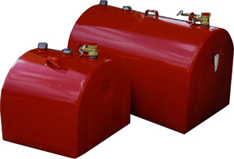
The Fuel Tank
The fuel tank for this project is from Tidy Tanks.
These portable tanks are made of steel and are certified for diesel or gasoline. They come
in various sizes.
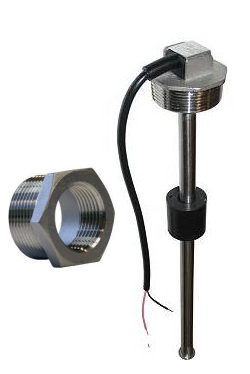
The Fuel Tank Level Sensor or Sending Unit
The fuel tank sending unit for this project is from Wema
USA. These fuel tank sending units are made of stainless steel and are very accurate. A
2 inch to 1.5 inch Iron Pipe reducer was needed to allow the sending unit to screw into the
fuel tank.
What you will need
One 10K resistor 1/4 watt. One Wema fuel sending unit that is the proper length to match
your fuel tank. One 2 inch to 1.5 inch Iron Pipe reducer (if you are using a Tidy Tank).
One RMS board with the newest firmware installed. Some wire (pink and black if possible).
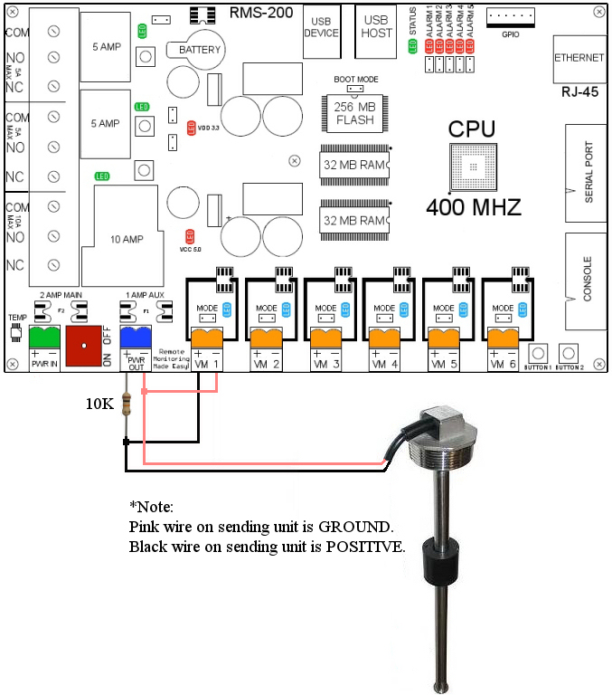
Wiring Diagram
The RMS comes with a 5 volt power output (blue connector). This is a good low power
source for use with a fuel sending unit. Using the diagram below as a reference
(RMS-200v1 shown, other RMS boards will be similar).
Connect ground (pink) wire from the WEMA sending unit to the negative output of the blue 5v power terminal
and to the negative input of one of the RMS voltmeters. Connect the sense (black) wire
from the WEMA sending unit to the 10k resistor. Connect the resistor to the positive output
of the blue power terminal. Connect a wire from the outside resistor lead to the positive input
terminal of one of the RMS voltmeters as shown below.
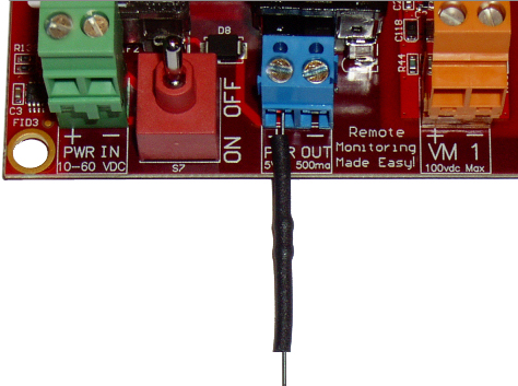
As a safety precaution, make sure the resistor is covered by some heat shrink tube or
electrical tape as shown below.
Theory of Operation.
The fuel sending unit is like a variable resistor that measures from 30 to 240 Ohms
depending on where the float is. Adding another resistor and measuring between the two
resistors creates a voltage divider. When the sliding float is at the top of the
fuel sender shaft, the RMS voltmeter reads approximately .0200 of a volt. When the
sliding float is at the bottom of the fuel sender shaft, the RMS voltmeter reads
approximately .1000 of a volt for a total range of .0800 of a volt. The voltage reading is
not very intuitive as to the level of fuel in the tank. Fortunately, there is an easy way
to display the voltage representation of fuel in the tank with a nice graphical gauge.
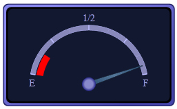
The graphical gauge above has 100 steps from empty to full. To get 100 steps in our voltage
range we must divide our total range(.0800) by 100. Therefore, each step on the gauge =
0.000800 of a volt. So to translate the voltage reading to a fuel level on the gauge use
the formula below.
PERCENT_FULL = (0.1000 - VOLTS) / 0.000800
To display the fuel reading on your RMS board download the gas gauge files.
Extract the zip file to your computer. Using FTP, upload all of the
extracted files (images folder, gas.xml, gg.php, jquery.min.js) to your RMS board at
/data/custom/
 Gas Gauge files
In the gg.php file, edit the lines starting at line 100 to suit your fuel tank and sending unit.
In the RMS web interface, navigate to the Setup page, then click on the Device Manager icon. Add a custom device. In the Name box put Gas Gauge, in the Path to CUSTOM file box put custom/gg.php in the Icon Path box put images/panel-gauge-16x16.png and click OK. A gas gauge icon will appear in the left navigation bar. Click on the new icon to see your gas gauge showing the fuel level of your gas tank.
Things of Note:
Due to the rounded top of the Tidy tanks the gas gauge will drop off
quicker in the top quarter of the tank reading. You may have to experiment with the values
to closer match your tank. The current going through the sending unit is less than 500
micro amps.
This concludes the remote fuel tank level sensor project. We can now remotely monitor our
fuel levels and make sure our generators never run out of fuel. We have our RMS board
email us whenever the tank is below 1/4 full.
Related Project: How to remote start a Honda generator.
LEGAL DISCLAIMER
WARNING: Electrical projects are inherently dangerous, and even the most benign task can
cause serious injury or death if not done properly.
ALWAYS READ AND FOLLOW INSTRUCTION MANUALS AND SAFETY WARNINGS OF TOOLS OR EQUIPMENT.
You must be particularly careful when dealing with electricity in the vicinity of petroleum
products such as gasoline - always use common sense. A spark near gas fumes can kill you!
Any advice, guidance or other information provided on this website or within any of our
publications cannot completely anticipate your situation. If you are at all unsure about
completing any aspect of this or other project, consult a qualified electrical contractor
to perform the service(s) for you.
ALWAYS follow electrical code requirements specific to your area, and before undertaking
any electrical project, contact your local electrical authority and your insurance company
to ensure that you comply with all policies, warranties, regulations and authorities
concerning this work.
YOU EXPRESSLY AGREE TO HOLD ETHERTEK CIRCUITS HARMLESS FOR ANY PROPERTY DAMAGE, PERSONAL
INJURY AND/OR DEATH, OR ANY OTHER LOSS OR DAMAGE THAT MAY RESULT FROM YOUR USE OF THE
INFORMATION OR SERVICE PROVIDED.
No advice or information, whether oral or written, obtained by you from us or through the
service, its employees, consultants and/or experts shall create any warranty not expressly
made herein.
The reader of the information on this web site agrees to assume all risk resulting from the
application of any of the information provided by EtherTek Circuits.
By using this web site, including any applets, software and content contained therein, the
visitor agrees that the use of this web site and its information or products is entirely at
his/her own risk.
Our Story
EtherTek Circuits started its business in 2001. Ever since we have provided remote monitoring and control solutions for Remote Tower Sites, the Oil & Gas industry, Telemetry systems for Agriculture, Municipalities, Mines, Solar Farms, Hydro Plants, and the Military.


